
What Are Bypass Capacitors
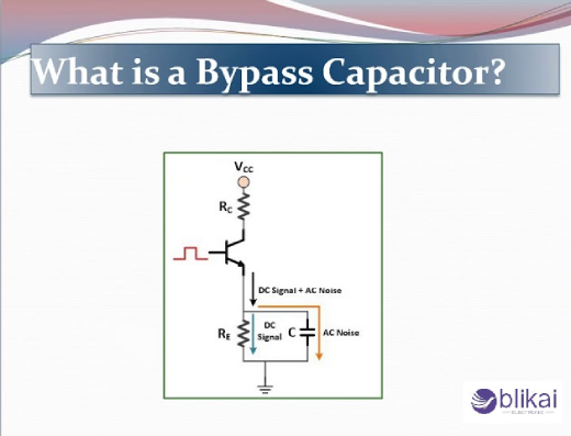
Understanding Bypass Capacitors
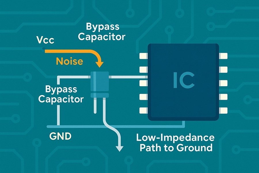
Bypass capacitors, or decoupling capacitors, are electronic circuit components which stabilize and suppress noise voltage. They are usually small in size and their capacitance values go down with time. This capacitor is, in fact, a local energy storage device aimed at applying the current burst to particular circuits or components at different values. Their fundamental role is to “bypass” high-frequency noise and abrupt voltage shifts to ground, hence guaranteeing a clean and stable power source for delicate electronic apparatus.
Types of Bypass Capacitors
There are several types of bypass capacitors, each suited for different applications:
Ceramic capacitors: Most common due to their low cost and small size
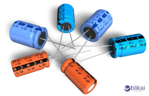
Electrolytic capacitors: Offer higher capacitance values but are physically larger
Tantalum capacitors: Provide excellent stability and reliability in compact sizes
Film capacitors: Known for their low noise characteristics and high voltage ratings
Common Applications of Bypass Capacitors
A. Digital circuits
The bypass capacitors maintain the integrity of the signals and help to minimize the noise in digital circuits. These bypass caps are essentially located very close to the power supply pins of ICs and provide a local charge source. This helps to suppress high-frequency noise and voltage spikes that can occur during rapid switching of digital signals. By doing so, bypass capacitors ensure stable operation of logic gates, microprocessors, and other digital components.
B. Analog circuits
Bypass capacitors tremendously help to provide stable voltage supplies to analog circuits and are also important in filtering noise. Power line bypass capacitors will filter high-frequency noise from power supply by operational amplifiers and other analog ICs so that there is more accurate processing of the signal involved. They also present a great way of instability and suppression of oscillations, thus improving the circuit’s stability-a fact that is most critical in analog applications with precision, audio systems, and sensor interfaces.
C. Mixed-signal systems
Mixed-signal systems contain both analog and digital components and, therefore, largely on bypass capacitors for the integrity of signals. These capacitors are effective in decoupling the analog and digital portions of a circuit, shielding sensitive analog signals from the onslaught of digital noise. This is especially crucial where data converters (ADCs and DACs) are concerned, as noise would heavily compromise purity and the associated accuracy of conversion.
D. Power supply decoupling
Among pernicious applications of bypass capacitors is power supply decoupling, placing these components near the power inputs of ICs and other components. This minimizes ripple on the power supply voltage and provides a stable power supply. This is even more critical for complex systems with multiple voltage domains or inclusion of switching power supplies capable of generating some noise.
E. RF and high-frequency circuits
Bypass capacitors are employed in RF and high-frequency circuits for the sake of maintaining signal integrity and minimizing unwanted coupling between different stages of a circuit. Bypass capacitors help to provide a low-impedance path to ground for high-frequency noise thereby reducing electromagnetic interference (EMI) and boosting general circuit performance. This is even more applicable to wireless communication systems in which signal quality is necessary for maintaining high data rates and long-range of communication.
Selecting the Right Bypass Capacitor
Capacitance value considerations
The capacitance value is very important when a capacitor is being selected for bypassing. The generally used value \(0.1-10µF; the range differs according to the application. In digital circuits, a 0.1µF is quite enough while in analog circuits the required would be higher than this. One needs to analyze the frequency of the noise that needs to be suppressed and the impedance of the power supply. A good rule of thumb is to pick the capacitance that shall provide low impedance at the frequency of interest.
Voltage rating requirements
Bypass capacitors should have a voltage rating much higher than the maximum voltage that will appear in the circuit. It is wise to leave at least a 25% margin for voltage spikes. For example, in a circuit operating at 5V, the capacitor should be rated for at least 6.25V. Keep in mind to consider the DC bias when selecting voltage ratings, as ceramic capacitors may lose capacitance.
Frequency response characteristics
Bypass capacitors should have low equivalent series resistance and low equivalent series inductance to remove the high-frequency noise. Ceramic capacitors are generally the first choice because of their superior performance at high frequencies. For broader frequency coverage, consider using multiple capacitors in parallel, each targeting a different frequency range.
Physical size and package options
The physical size of the bypass capacitor affects its performance and placement. Smaller packages (e.g., 0402, 0603) have lower parasitic inductance, making them better for high-frequency applications. However, they also have lower capacitance values. Larger packages can provide higher capacitance but may introduce more parasitic effects. Consider the available space on your PCB and the required capacitance when choosing the package size.
Conclusion
A bypass capacitor is, in short, an essential part of an electronic circuit because it acts as a military against unwelcome and unfriendly noise intrusion and fluctuation of voltage. These little, tough components see use in practically every application-from power supply smoothing to protecting very delicate components; they serve chiefly to uphold the integrity of a signal and enhance circuit performance.